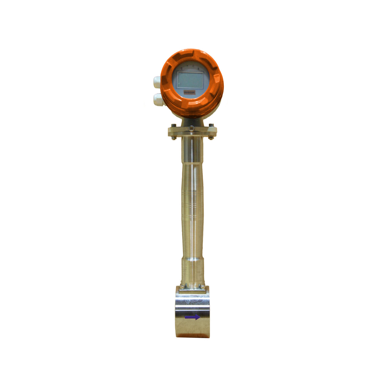
Vortex Shedding Flow Meter — BF50
BF50 vortex flow meter measures liquids, gases and steam (saturated and superheated) via Kármán vortex shedding. The passive smart version suits sites without a power supply; the remote version works with displays, controllers and computers. With temperature/pressure compensation modules it outputs accurate mass flow for steam and gas.
Specifications
| Accuracy | ±1 (special calibrated ±0.5) |
| Repeatability | 0.2 (special 0.1) |
| Turndown | 10:1 typical, up to 25:1 |
| Nominal size | DN15 – DN500 mm; insertion DN200 – DN6000 |
| Media temperature | -40 to +300 °C (superheated steam to 350 °C) |
| Media pressure | ≤2.5 MPa (up to 10 MPa on order) |
| Vibration | <2g acceleration |
| Straight run | 15D upstream / 5D downstream |
| Ex rating | Ex ib IIC T1~T4; Ex d IIC T1~T4 |
| Protection | IP65 / IP67 / IP68 |
| Output | 4–20mA, pulse/frequency; RS485, Modbus, HART |
Details
Working Principle
A bluff body in the flow alternately sheds regular vortices (Kármán vortex street). f = Sr·U1/d. The pulse frequency is proportional to velocity; with the pipe section the volumetric flow is derived (qv = πD²U/4). Within a suitable Reynolds range the meter coefficient depends only on geometry — immune to medium viscosity and density. For gas/steam mass flow, temperature or pressure compensation is applied.
Structure
Sensor and converter. The converter consists of a preamplifier, filtering/shaping circuits, D/A conversion, output interface, terminals and a protective cover. Smart versions have a built-in microprocessor with display and communication. No moving parts; no impulse lines or 3-valve manifold required (compared with DP throttling).
Installation
- Ensure adequate straight pipe (typically 15D upstream, 5D downstream)
- Keep away from pumps and valves (strong vibration sources)
- Liquid: avoid air pockets; gas: avoid liquid collection
- Horizontal or vertical; upward flow recommended on vertical liquid lines
Model / options selection
| Item | Options |
|---|---|
| Nominal size | DN15–500 mm in-line; DN200–6000 insertion |
| Power | A: external supply with display; B: battery supply with display |
| Compensation | C: P&T full compensation; D: temperature only; E: pressure only; F: none |
| Converter form | 1: integral; 2: remote/split |
| Housing material | 1: stainless steel; 2: special |
| Bluff body material | 1: stainless steel; 2: special |
| Flange standard | GB / AS / HG / JB |
| Pressure rating | PN1.6 / PN2.5 / PN4.0 etc. |
| Output signal | 4–20mA, pulse, HART/Modbus |
| Explosion | None / Ex d IIC T4 |